ac capacitor wiring diagram
CBB65Universal model Shell material. The wiring for the AC condenser fan motor will likely have the black wire noted in the wiring diagram go directly to the compressor contactor.

Pin On Alignment
These electric motors are powered using a single-phase or three-phase alternating current.
. Metallized polypropylene film Capacity. One wire will always go to the compressor which you can verify using your factory wiring diagram or tracing them out. Citation neededThere are two common types of motor capacitors.
Voltage de-rating factor Safety agency. The one to remove can go to a relay a second capacitor called a start capacitor or a PTC device which is a small disk. The AC 12hp DC garage door opener wiring diagram for harnesses have a high voltage and low voltage wire harnesses that connect to different components in the operator below is a description of which wires connect to which components.
BOJACK Dual run circular start capacitor Ombines two capacitors into one unit. What can be a Wiring Diagram. Refer to the motor manufacturers data on the motor for wiring diagrams on standard frame Ex e Ex d etc.
In the case of AC single-phase induction motors this accessory is the capacitor. When we select the voltage rated for capacitorwe must know the value of our power supplyFor safety purposemultiply the voltage of power supply with 30Factors that affect the selection of the proper voltage rating of the capacitor include. A wiring diagram is a straightforward visual representation in the physical connections and physical layout of your electrical.
First step is stepping down the 220 volts of AC supply into small voltage. Electric motor starting run capacitor troubleshooting FAQs Questions Answers about Electric Motor Start-Boost or Run Capacitors Capacitors are electric devices that get an electric motor running at start-up or that help keep a motor running once it has started. The article also contains the purpose and benefits of creating a wiring diagram.
A motor capacitor such as a start capacitor or run capacitor including a dual run capacitor is an electrical capacitor that alters the current to one or more windings of a single-phase alternating-current induction motor to create a rotating magnetic field. What is often a Wiring Diagram. Unlike a pictorial diagram a wiring diagram uses abstract or simplified shapes and lines to show components.
See an image of the wiring diagram. Pictorial diagrams are often photos with labels or highly-detailed drawings of the physical components. Various calculations must be performed during the electrical design stages of any project to deliver a safe electrical system for the end user.
There are basically four steps involved in making a cell phone charger. Energy and Power Inside the capacitor bank panel. Wiring Diagram Pictures Detail.
Power factor correction calculation and schematics. Run capacitors and start capacitors. Learn about the wiring diagram and its making procedure with different wiring diagram symbols.
The inverter is made to give a voltage of 220V AC or 110V AC to the device connected with it at the output socket as a load. That means they will be wired differently in the condenser. The symbol is used with a b and can also be shown as a filter to pass AC signals and to block DC signals.
You may hear it humming or. Second step involves rectification of AC into DC by using a full wave bridge rectifier. Zoom_in Parts Diagram Reference7.
Motor Capacitor 53uF-64uF 220V K030B0532-1. The basic working principle of AC motor is the rotating magnetic field RMF generated by the stator winding when an alternating current is passed through it. Many electric motor systems require peripheral accessories to ensure a safe and efficient operation.
Wiring Diagram Images Detail. 12 volt relay wiring diagram 5 Pin Bosch Relay Wiring Diagram. Wiring Diagram For Rail Trolley Garage Door Operators.
Inst Maint Wiring_5qxd 20112015 1137 AM Page 6. A wiring diagram is a straightforward visual representation in the physical connections and physical layout of an electrical system or. How is a Wiring Diagram Different from a Pictorial Diagram.
Furthermore the heat pump condenser fan motor will not. Most symbols used on a wiring diagram. Since the DC voltage obtained in second step contains AC ripple which is removed using filtration process.
Capacitor - A capacitor is a storage unit of electric charge. Install the new capacitor with the same setup and wiring as the old capacitor. One may be a compressor monitoring wire and should be preserved and is explained in the next step.
Our AC unit stopped working we had a tech that came out that said we needed to replace the Capacitor. Three terminals on the top are labeled HermH for the compressor motor FanF for the fan and C for the common lineIt will power a compressor motor and a fan motor Model. How to hook up an electric motor start or run capacitor.
Finally resume power to the system and test the motor. From the relay the AC will pass to the load that is managed by the line voltage. The original Capacitor is CBB65B 405 uf 5 440 VAC 5060Hz 407021.
If the capacitor has failed the symptom is that the motor wont start. These diagrams are current at the time of publication check the wiring diagram supplied with the motor. This article gives electric motor start-run capacitor installation wiring instructions for electric motor capacitors designed to start run an electric motor such as an AC compressor heat pump compressor or a fan motor and how to wire up a hard-starting air conditioner.
Emerson motor wiring diagram Dayton Motor Wiring Solutions 17. 141 thoughts on HVAC Start and Run Capacitor Explained and Replacement Elaine August 3 2022. Electric motor start-run capacitor instructions.
The wiring for the heat pump condenser fan motor will be slightly different. When the AC main supply is open the inverter sensors consider it and pass this AC to the relay plus battery charging section. 2 Determine the voltage rating for capacitor.
Standard Wiring Diagram Symbols. The AC electric motor converts AC Alternating Current electrical energy into mechanical energy.

Domestic Refrigerator Starting Relays Refrigerator Compressor Refrigeration And Air Conditioning Electrical Circuit Diagram

Air Conditioner C S R Wiring Diagram Compressor Start Full Wiring Fully4world Refrigeration And Air Conditioning Hvac Air Conditioning Hvac Air

Air Compressor Capacitor Wiring Diagram Before You Call A Ac Repair Man Visit My Blog For Some Electrical Wiring Diagram Compressor Electrical Circuit Diagram

Unique Wiring Diagram Ac Split Mitsubishi Hvac Air Conditioning Refrigeration And Air Conditioning Air Conditioner Compressor

Ac Wiring Carrier Ac Air Conditioning Maintenance

Danfoss Relay Oil And Capacitor Type Connection With Diagram In Urdu Hindi Fully4world Refrigeration And Air Conditioning Hvac Air Conditioning Capacitor

55 New Potential Relay Wiring Diagram Electrical Circuit Diagram Ac Capacitor Electrical Diagram

Pin On Diagram Template

Unique Fan Relay Wiring Diagram Hvac Diagram Diagramsample Diagramtemplate Wiringdiagram Diagramchart W Ac Wiring Electrical Circuit Diagram Ac Capacitor

Pin On Split Ac

Pin On Diy Electrical

Blower Motor Wiring Diagram Ac Condenser Fan Motor Wiring Diagram Air Compressor Pressure Switch Diagram Compressor

50 Best Of Compressor Start Relay Wiring Diagram Circuit Diagram Ac Capacitor Electrical Circuit Diagram

Pin On Klima
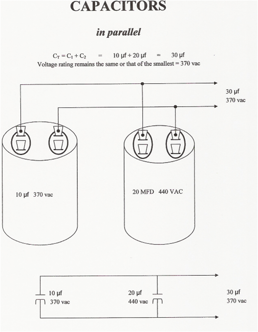
Parallel Wiring Capacitors Capacitor

Wiring Diagram Ac Window Refrigeration Refrigeration And Air Conditioning Diagram Air Conditioner

How To Diagnose And Repair An Air Conditioner Capacitor Refrigeration And Air Conditioning Air Conditioner Hvac Air Conditioning

Capacitors For Compressor Wiring Diagram Hvac Compressor Compressor Ac Capacitor

Air Conditioner Compressor Wiring Diagram Before You Call A Ac Repair Man Visit My Blog Air Conditioner Capacitor Refrigeration And Air Conditioning Ac Wiring